
Class H Amplifier PDF Electricity Electronic Engineering
welcome to Dasjee project solutions -Class H power amplifier design and resultby increasing transistor in driver stage we can increase wattage.thank youcomme.

Class H Professional Power Amplifier Circuit Diagram Class h 2000 watt amplifier circuit
A class H amplifier circuit includes a Buck converter 20 and a charge pump 30 which are used to generate voltages which are used in turn to power an output driver 10 . A feedback path 36 controls the loop. The circuit is particularly suitable as a high efficiency circuit for driving headphones or loudspeakers.
Class H Professional Power Amplifier Circuit Diagram / LM3886 Power Sub Woofer Amplifier
If so, then a Class H Power Amplifier Schematic Diagram (CHPASD) is exactly what you need. A CHPASD is an advanced type of amplifier design that allows you to generate more power than with a traditional Class A amplifier. This is because the CHPASD features a unique power supply design that can be configured to switch between a low level and a.

Pro Audio Purwokerto HBGR1K Power Amplifier Class H
The Class H amplifier had an efficiency above the Class AB amplifier by 5-7% from 5-30mW of output power without affecting the total harmonic distortion (THD) at the design specifications. The Class H amplifier design met all design specifications and showed performance comparable to the designed Class AB amplifier across 1kHz-20kHz and 0.01mW.

Class H Amplifier Circuit Diagram How To Build A Class D Power Amp Projects Class h is an
Class G and Class H are quests for improved efficiency over the classic Class-AB amplifier. Both work on the power supply section. The idea is simple. For high-output power, a high-voltage power supply is needed. For low-power, this high voltage implies higher losses in the output stage.

Class H Amplifier Circuit Diagram / Class G And Class H Ic tda1562q is class h power amplifier
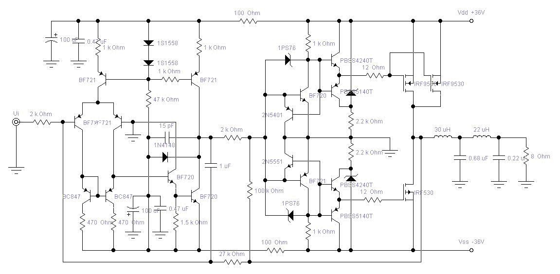
In your circuit the "take lower E" switching limit is V=34V. In class H amplifiers E is taken from a varying output switch mode power supply which tries to stay a little higher than the needed V. The smaller is the difference E-V the lower are the losses in the transistor between E and the load.

class h amplifier circuit diagram Wiring Diagram and Schematics
Class H Powerful amplifier circuit 2000W. Class H is an analog amplifier which aims to improve the efficiency of the amplifier B / AB class. In class B / AB, the supply voltage is only one pair which is often denoted as + VCC and -VEE for example + 24V and -24V (or written with +/- 24volt). In class H amplifiers, the supply voltage is multilevel.

1000W Power Amplifier Class H Kencleng Pro Electronic Circuit
Figure 3 - Basic Principle of Class-G Amplifier. The output stage above will be used for all further analysis of the Class-G output stage. The front-end and VAS (voltage amplifier stage) are virtually identical to any normal Class-B amplifier. The VAS would normally be used in place of one of the current sources shown.

Class H Amplifier Circuit Diagram / Gated Class H Amplifier Line Driver System And Method
The circuit diagram of the 2000W class AB power amplifier uses 7 pairs of MJ15003 and MJ15004 transistors for the final amplification block. The circuit operated with 90V DC symmetrical (dual polarity) power supply circuit. The transistors must be mounted on the heatsink to prevent overheating, maintain the transistor's work in maximum.

CLASS H AMPLIFIER EasyEDA open source hardware lab
In Douglas Self's book, Audio Power Amplifier Design Handbook, he describes class-H amplifiers thus: Class-H Class-H is once more basically Class-B, but with a method of dynamically boosting the single supply rail (as opposed to switching to another one) in order to increase efficiency [12]. The usual mechanism is a form of bootstrapping.

Class h amplifier circuit study part 2 YouTube
The schematic diagram of a Class H amplifier provides a comprehensive visual representation of its circuits and components. It outlines the connections and interactions between different parts of the amplifier, such as the power supply, voltage rails, input and output stages, and protection mechanisms..

Class h amplifier with pcb layout
Hello Friends I m Hridoy Borman In This Video I m going to tell You about class h amplifier working system how it's work and how u can make a class h amplifi.

SKEMA CLASS H Resources EasyEDA
3.Supports simple circuit simulation. 4.For students, teachers, creators. Profession.. CLASS H AMPLIFIER HQX2400. Design Drawing schematic diagram ( 1 / ) Sheet_1. Open in Editor PCB ( 1 / ) PCB_CLASS H AMPLIFIER_2. Open in Editor.

Class H Professional Power Amplifier Circuit Diagram Class H Power Amplifier Circuit 2000w
The circuit diagram for a Class H audio amplifier is designed to let you see how the various components of the amp work together to provide high-quality amplification. By studying this diagram, you can learn about the various components of the amp, such as the power supply, transistors, and resistors. Additionally, you can see how the circuit.

Class H Amplifier Circuit Diagram / Stk413 000 Datasheet Pdf Audio Power Amplifier Hybrid Ic
Section 5.2 Class A Power Amplifiers. •The limitations due to the efficiency of class A power amplifiers. •Trans former coupled Class A power output stages. Section 5.3 Class B Amplifiers. • Class B biasing. • Class B biasing. • Push -pull output. • Adva ntages & disadvantages of class B. Section 5.4 Push -pull Driver Stages.

koleksi skema power ampli by pyon sound skema power class H
Definition. Class H amplifiers modulate the supply voltage to the amplifier output devices so that it is never higher than necessary to support the signal swing. This reduces dissipation across the output devices connected to that supply and allows the amplifier to operate with an optimized class AB efficiency regardless of output power level.
